
Products
Experience The Best World-Class Comprehensive Energy Service Provider
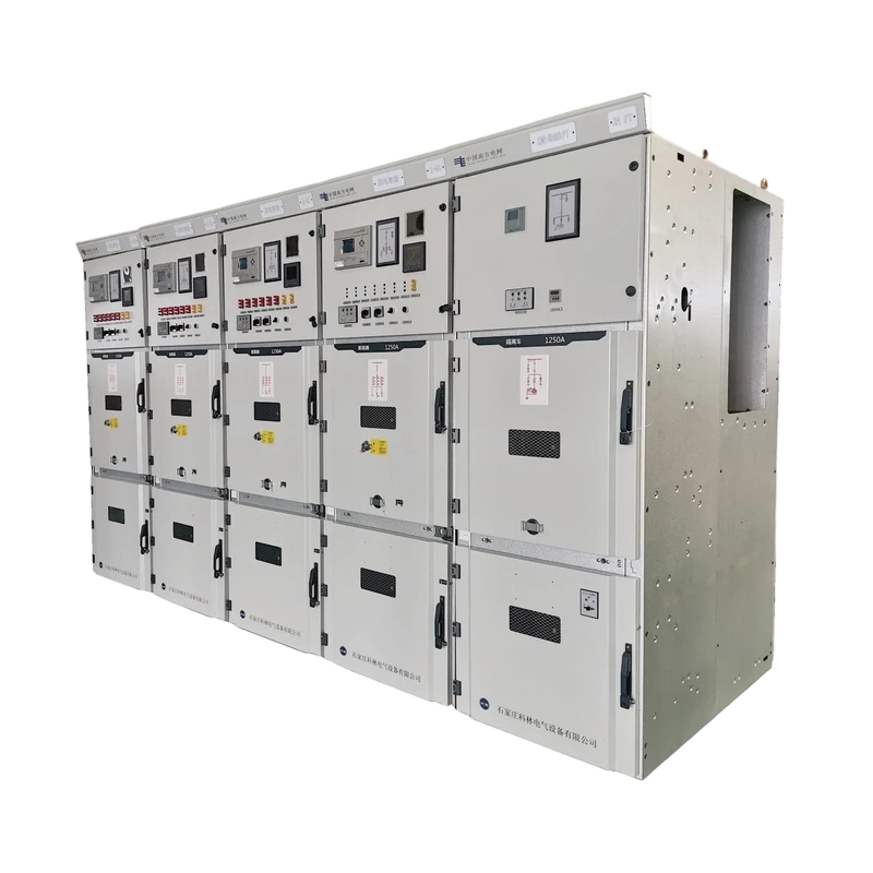
KYN28A-12 (GZS1) AC Metal-Clad Withdrawable Switchgear
KYN28A-12(GZS1) AC metal-clad withdrawable switchgear (hereinafter referred to as switchgear) is a complete set of power distribution equipment for three-phase AC 50Hz single-busbar and sectionalized single-busbar systems.

KYN28A-12 (GZS1) AC Metal-Clad Withdrawable Switchgear.pdf
Product Details
KYN28A-12(GZS1) AC metal-clad withdrawable switchgear (hereinafter referred to as switchgear) is a complete set of power distribution equipment for three-phase AC 50Hz single-busbar and sectionalized single-busbar systems. It is mainly used for power supply from power plants and small- and medium-sized generators, power distribution of industrial and mining enterprises, and transformation and power transmission in secondary substations in power systems, and starting of large high-voltage motors, etc., for control, protection and monitoring purposes. This switchgear meets the requirements of IEC298 and GB/T 3906-2020 and other standards. It has the interlocking functions of preventing racking of the circuit-breaker truck under load, preventing mis-operation (accidental close/open) of the circuit breaker, preventing closing the circuit breaker when the earthing switch is in the closed position, preventing accidental access to live compartments, and preventing closing of the earthing switch while the circuit is live. It can be fitted with our in-house VKL or ZN63A vacuum circuit breaker. It is a high-performance power distribution device.
Technical Specifications
|
Model |
KYN28A-12(GZS1) |
Rated Voltage |
3.6, 7.2, 12kV |
|
Rated Insulation Level |
Power-frequency withstand voltage: 42 kV (1 min); Lightning impulse withstand voltage: 75 kV (peak) |
Rated Frequency |
50Hz |
|
Main Busbar Rated Current |
630, 1250, 1600, 2000, 2500, 3150, 4000, 5000A |
Branch Busbar Rated Current |
630, 1250, 1600, 2000, 2500, 3150, 4000*, 5000A |
|
Rated Short-time Withstand Current (RMS, 4 s) |
16, 20, 25, 31.5, 40, 50kA |
Rated Peak Withstand Current** |
40, 50, 63, 80, 100, 125kA |
|
Degree Of Protection |
IP4X for the enclosure; IP2X between compartments and when the circuit breaker compartment door is open |
* Branch busbar rated current can reach 4000A with air cooling
** The short-circuit capacity of the current transformer should be considered separately
Structure and Features
The switchgear consists of two major parts: the fixed cabinet and the withdrawable part (i.e., handcart). The shell of the cabinet and the partition of functional units are assembled from aluminium-zinc (Al-Zn) alloy-coated steel sheet. The enclosure protection rating of the switchgear is IP4X, and when the circuit breaker compartment door is open, the protection rating is IP2X. This cabinet has the functions of overhead incoming and outgoing lines, cable incoming and outgoing lines, and left-right connection. According to the purpose, the switch cabinets of each scheme can be arranged into a power distribution device that can complete the design function. Since the installation, commissioning and maintenance of the switchgear can be carried out from the front, the switchgear can be installed against the wall and back-to-back to form a double arrangement, which has the advantages of saving floor space and reducing total investment.
Cabinet
The cabinet of the switchgear consists of four parts: front cabinet, rear cabinet, instrument room, and pressure relief device. These four parts are independently assembled and then spliced together. Since the shell and partition of each part are made of aluminium-zinc (Al-Zn) alloy-coated steel sheet processed and bent by CNC machine tools and then bolted, the assembled switchgear can maintain dimensional uniformity. It provides excellent corrosion resistance and higher mechanical strength than conventional steel plate. The switchgear is divided by partitions into handcart compartment, busbar compartment, cable compartment, and relay instrument compartment. Each unit shell has independent grounding, and the protection rating between compartments reaches IP2X. Except for the relay instrument compartment, the other three compartments each have their own pressure relief channels. Thanks to its centre-mounted (withdrawable) design, the cable compartment position is greatly increased, so the equipment can connect multiple cables.
Handcart Compartment
The handcart compartment is equipped with specific guide rails for the circuit breaker handcart to slide and work inside. A shutter mechanism is installed at the front end of the static contact, thereby ensuring the safety of operators and maintenance personnel.
Busbar Compartment
The busbar compartment is used for main busbar installation. In addition, there are three holes on the left side wall for installing busbar insulating bushings, separating the busbar compartments between equipment and preventing accident expansion.
Cable Compartment
The cable compartment can be installed with current transformers, earthing switches, surge arresters and cables, and its bottom is equipped with a slotted removable non-metallic sealing plate or non-magnetic conductive metal sealing plate to ensure on-site construction convenience.
Instrument RoomThe instrument room is used to install various relays, instruments, signal indications, operating switches and other components. In addition, according to user requirements, a small busbar room can be added on top of the instrument room, accommodating up to fifteen auxiliary busbars.
Pressure Relief Device
Pressure relief devices are installed above the handcart compartment, busbar compartment, and cable compartment. When an internal arc fault occurs in the circuit breaker or busbar or cable compartment, accompanied by the appearance of the arc, the internal air pressure of the switchgear rises. After reaching a certain pressure, pressure-relief flaps on the roof open automatically to relieve pressure and vent the arc gases to ensure the safety of operators and switchgear.
Prevention of Misoperation Interlocking Device
The switchgear is equipped with a safe and reliable interlocking device, fully meeting the "five prevention" requirements.
The instrument room door is equipped with indicating (mimic) buttons or KK changeover switches to prevent mistaken closing and opening of the circuit breaker.
The circuit breaker can only be opened and closed when the circuit breaker handcart is in the test or working position, and after the circuit breaker is closed, the circuit breaker cannot move, preventing racking of the circuit-breaker truck under load.
The circuit breaker is interlocked with the earthing switch mechanism. Only when the circuit breaker handcart is in the test position or withdrawn from the cabinet can the earthing switch be closed, and at the same time the handcart cannot enter the working position. When the handcart is in a non-test position inside the equipment, the earthing switch cannot be closed, thus preventing closing the earthing switch when live and closing the circuit breaker before the earthing switch is opened.
When the circuit breaker is in the working position, the lower door and rear door cannot be opened, preventing accidental access to live compartments.
The circuit breaker handcart is confirmed to be in the test or service position, and there is no control voltage, only manual opening is possible, not closing (this interlock can be omitted according to customer requirements).
When the handcart is in the working position, the secondary plug is locked and cannot be removed.
Electrical interlocking can be installed between switchgear panels (units). Switchgear without earthing switch can be equipped with electromagnetic lock to prevent accidental access to live compartments.
Applications
Mainly used for power supply from power plants and small- and medium-sized generators, power distribution of industrial and mining enterprises, and transformation and power transmission in secondary substations in power systems, and starting of large high-voltage motors, etc., for control, protection and monitoring purposes.
Scope of Use and Precautions
Applicable range:
Use environmental conditions:
Altitude not exceeding 1000m. When the altitude exceeds 1000m, handle according to JB/Z102 "Technical Requirements for High-voltage Apparatus Used in Altitude Areas". When the altitude does not exceed 2000m, secondary auxiliary equipment does not require any measures.
Ambient temperature: −25 °C to +40 °C. Air relative humidity: daily average not greater than 95%, monthly average not greater than 90%. When the temperature drops suddenly, condensation may occur, accompanied by pollution. This product is suitable for the following two environmental conditions that are more severe than normal conditions.
a. Infrequent condensation with mild pollution.
b. Generally no condensation (average no more than twice a year) with relatively severe pollution.
Seismic intensity not exceeding 9 degrees.
Places without fire, explosion, severe pollution, chemical corrosion and severe vibration. If there are special requirements, the user and manufacturer shall negotiate.
When the actual use conditions are different from the above, the user and manufacturer shall negotiate.
Precautions:
Switchgear grounding device:
Use the pre-installed connecting bars to join the earthing busbars of adjacent units.
Connect all leads that need grounding inside the switchgear.
Connect the foundation frame to the grounding bar. If the equipment arrangement exceeds 10 units, there must be more than two grounding bars.
Transportation and storage:
During transportation and storage of switchgear, the following points should be noted:
Do not tip over, invert or suffer severe vibration, and keep it away from open flames and heat sources;
Prevent rain to avoid product dampness;
Do not dismantle any electrical components or parts without authorisation.
The product is supplied as a complete set with the following documents:
Product certificate;
Secondary wiring diagram;
Product instruction manual;
Equipment list.
Ordering instructions:
The following information should be provided when ordering:
Main wiring scheme number and single-line system diagram, arrangement diagram and floor plan;
User provides secondary schematic diagram and terminal arrangement diagram. If there is no terminal arrangement diagram, it shall be arranged by the manufacturer;
Model, specification and quantity of electrical components in the switchgear;
Electrical equipment summary table;
If the switchgear is used in special environmental conditions, this shall be stated at the time of ordering;
If additional or spare accessories are required, specify their type and quantity.
Typical Solution
Smart Distribution Network Solution
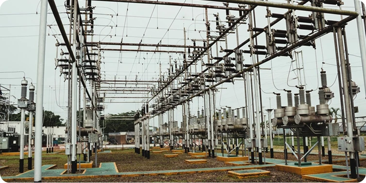
This solution is designed directly for power users and is closely related to production and daily life. It is suitable for medium- and low-voltage distribution networks, including overhead and cable lines. Working together with the distribution master station, it enables real-time monitoring of the power distribution network, fast fault location, isolation, and restoration of power to non-fault areas.

Smart Substation Product Solution
Utilizes a dual 32-bit high-speed CPU multi-processor architecture and an embedded real-time operating system. A reliable startup mechanism enhances fault sensitivity and enables cross-platform and cross-hardware applications.

Smart Integrated Electricity Utilization System Solution
Designed with an open interface and compliant with domestic and international technical standards, the system provides an integrated solution for various users, including grid-connected users, substations, high/low-voltage commercial and industrial users, low-voltage residential users, and property/community energy management users. It aims to address challenges such as fluctuating power supply and demand, difficulty in electricity fee collection, high bad-debt risks, and their impact on the economic efficiency of power supply enterprises. The system enables remote meter reading, electricity sales management, property management, energy consumption monitoring, power quality analysis, smart line monitoring, and free interaction of electricity information. It offers flexible, efficient, accurate, and user-friendly technical features, providing abundant, timely and reliable data for energy market analysis.
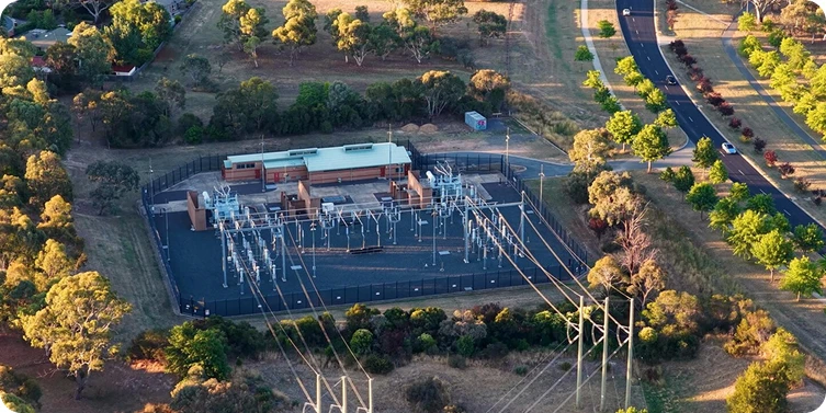
Smart Power Distribution System Solution
As an integrated primary & secondary power distribution solution, it features advanced technology, flexible configuration, high efficiency and intelligence. It fully meets the requirements of intelligent power distribution from 0.4kV to 40.5kV, supporting smart and eco-friendly urban development and providing reliable support for smart grid construction.
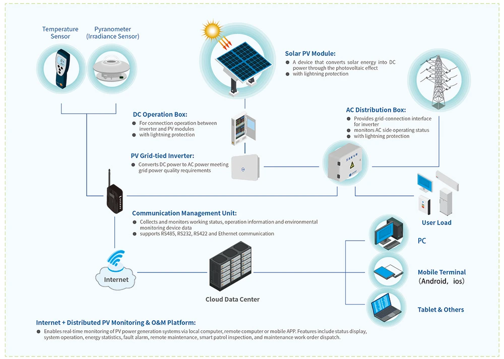
PV-Storage-Charging Smart Microgrid Solution
Drawing on nearly two decades of expertise in power system technology, we integrate PV inverter, power protection, communication and internet technologies to deliver full-lifecycle integrated solutions for distributed PV power stations, including utility-scale and energy storage PV power stations.
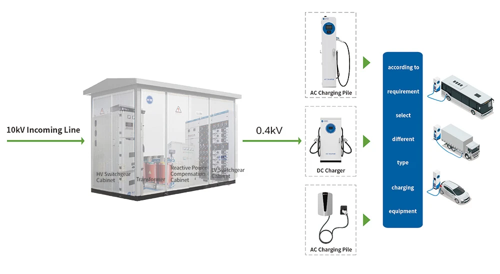
A complete EV charging solution comprising smart charging equipment, cloud platform and mini-program, covering AC and DC chargers, operation platform and customized mini-program development.
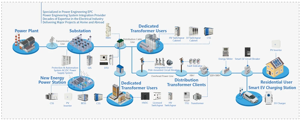
Power Engineering System Integration Solution (EPC)
Kelin Power Engineering EPC leverages the brand, technology, capital and market advantages of Kelin Electric. Focused on power engineering construction, we have established a full lifecycle service model of "Design + Procurement + Construction", striving to deliver premium projects in the power industry.
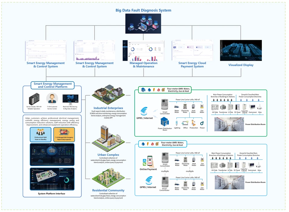
Smart Energy Management & Control Platform
Focused on integrated energy management, and drawing on extensive power system experience combined with the company's full product range, we provide premium integrated energy management and control solutions for enterprise parks, residential communities and urban complexes based on Internet thinking.
Find Solutions, Not Just Suppliers
If you are interested in any of our products or would like to make your customized order, please feel free to contact us. We are looking forward to establish successful business relations with you.
Discover More