
Products
Experience The Best World-Class Comprehensive Energy Service Provider
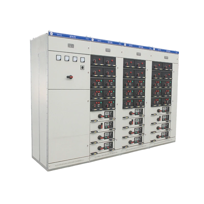
MNS LV Withdrawable Switchgear
MNS switchgear is assembled from modular components and is a modular, withdrawable low-voltage switchgear assembly (hereinafter referred to as the device). It is suitable for AC 50/60Hz power supply systems with rated operational voltage up to 690 V, and is used for the control of power generation, transmission and distribution equipment, and of energy-conversion and consumption equipment.

MNS LV Withdrawable Switchgear.pdf
Product Details
MNS switchgear is assembled from modular components and is a modular, withdrawable low-voltage switchgear assembly (hereinafter referred to as the device). It is suitable for AC 50/60Hz power supply systems with rated operational voltage up to 690 V, and is used for the control of power generation, transmission and distribution equipment, and of energy-conversion and consumption equipment. This device complies with IEC439, VDE660 Part 5 and GB/T7251.2-2023 "Low-voltage switchgear and controlgear assemblies" national standard, JB/T9661-1999 "Low-voltage withdrawable switchgear assemblies" professional standard.
Technical Specifications
|
Rated Insulation Voltage |
1000V |
Rated operational voltage (Ue) |
690 V |
|
Rated current of main busbar |
up to 6,300 A |
Main Busbar Short-time (1S) Withstand Current |
100kA (RMS) |
|
Main Busbar Rated Peak Withstand Current |
220kA (Maximum) |
Distribution Busbar (Vertical Busbar) Maximum Working Current |
1600A |
|
Distribution Busbar (Vertical Busbar) Rated peak withstand current |
105 kA |
Degree of protection |
IP42 |
Applications
Suitable for AC 50-60Hz power supply systems with rated operational voltage up to 690 V. Switchgear types: Power Distribution Centre (PC) is equipped with ME, F, M and AH series breakers. Motor Control Center (MCC) is assembled from large and small drawers; the main switch of each circuit adopts high-breaking-capacity moulded-case circuit breaker (MCCB) or a rotary fuse-switch. Power-factor automatic compensation cubicle.
Scope of Use and Precautions
Applicable range:
Normal use environmental conditions:
Ambient air temperature not higher than +40℃, not lower than -25℃, and the average temperature within 24h not higher than +35℃.
Atmospheric conditions: clean air, relative humidity not exceeding 50% at the highest temperature +40℃, higher relative humidity allowed at lower temperatures, for example 90% at +20℃, but considering temperature changes, occasional condensation may occur.
Altitude: not exceeding 4,000 m.
This device can withstand transport and storage at temperatures between −25 °C and +55 °C, with short-term excursions (≤ 24 h) up to +70 °C. Under these extreme temperatures, the device should not suffer any irreversible damage and should be able to work normally under normal conditions.
If the above use conditions cannot be met, this shall be agreed between the user and the manufacturer.
When this device is used for offshore oil drilling platforms and nuclear power plants, a separate technical agreement should be signed.
Precautions
Installation, use, maintenance:
The outline dimensions of the device are shown in Figure 4, and installation references are shown in Figures 5 and 6.
After the device arrives at the destination, first check whether the packing box is intact. If the device is not installed immediately, it should be stored in a dry and clean place.
The device is recommended to be installed away from the wall. It can also be installed against the wall, but the cabinet width should be changed to 1000mm. The installation foundation plane is required to be flat, the levelness tolerance of the foundation channel is ≤ 1/1000 and the total length deviation is ≤ 3 mm.
MCC package includes two sizes of cable-end sleeves and a quantity of copper lugs for secondary circuits. (To suit crimped copper lugs, multi-core flexible wires are recommended for secondary cables.)
After connecting the cables, the bottom of the device should be sealed to prevent small animals from climbing into the cabinet and causing short-circuit accidents.
After installation and adjustment, or before putting into operation, the following inspections and tests are required:
Check that the electrical and control wiring complies with the factory drawings.
Operate all switches manually; they should move smoothly without abnormal resistance or jamming.
Check whether the mechanical interlocking mechanism and electrical interlocking device operate correctly and reliably, and whether they meet system requirements.
Check whether the insulation resistance of the main circuit and control circuit meets the specified requirements; check whether the electrical equipment installed in the device is in good contact and meets the technical conditions of the electrical equipment itself.
Check whether there are foreign objects inside the device and whether the mounting screws of each component are loose.
Withdrawable MCC operation instructions:
The bottom of the drawer should be correctly inserted into the guide before pushing into the cabinet, otherwise it will cause damage to the drawer or inability to pull out.
The symbols and functions on the 8E/4 and 8E/2 drawer panels are shown in Figure 2. The arrow from disconnected (isolated) position "0" to working position "1" in the figure indicates: first push the operating handle inward, then rotate the handle from "0" to "1". When returning, no push is needed, just rotate the handle from "1" to "0", and after releasing, the handle automatically pops out.
The symbols and functions on the 8E-24E drawer panels are shown in Figure 3. When the handle reaches the working position "on/off", the mechanism releases the mechanical lock on the main switch, and only then can the main switch be closed or opened. However, after the main switch is closed, the handle of the interlocking mechanism cannot be operated.
There is a small plastic cover at the lower right corner of the symbol mark. This is the door unlocking mechanism. The operation process is as follows: when the drawer is in the working position, if you want to open the door, first pull out the small cover. Then insert a screwdriver into the hole and move the lock downward to open the door. After closing the door, be sure to cover the plastic small cover, otherwise the declared degree of protection is no longer maintained.
Key Features
Compact designaccommodates more functional units in a smaller space.
Strong structural versatility and flexible assemblyC-section profiles on a 25 mm modular grid (E = 25 mm) can meet the requirements of various structural forms, protection ratings and use environments.
Standard modular designcan be configured for protection, switching, conversion, control, measurement and indication functions
Functional unitsusers can freely select and assemble functional units to suit their needs.
Safetyhigh-strength flame-retardant engineering plastic components are used to effectively enhance protection and safety performance.
High technical performancekey ratings meet current international technical levels.
Site spacehigh degree of modularity (compact, intelligent and diversified design), which can greatly reduce the storage and transport space required for prefabricated parts and make full use of the distribution room space.
Convenient assemblyno special complex tools are required.
Typical Solution
Smart Distribution Network Solution
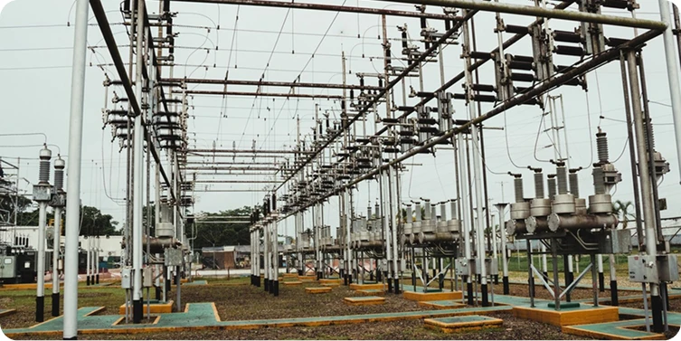
This solution is designed directly for power users and is closely related to production and daily life. It is suitable for medium- and low-voltage distribution networks, including overhead and cable lines. Working together with the distribution master station, it enables real-time monitoring of the power distribution network, fast fault location, isolation, and restoration of power to non-fault areas.

Smart Substation Product Solution
Utilizes a dual 32-bit high-speed CPU multi-processor architecture and an embedded real-time operating system. A reliable startup mechanism enhances fault sensitivity and enables cross-platform and cross-hardware applications.

Smart Integrated Electricity Utilization System Solution
Designed with an open interface and compliant with domestic and international technical standards, the system provides an integrated solution for various users, including grid-connected users, substations, high/low-voltage commercial and industrial users, low-voltage residential users, and property/community energy management users. It aims to address challenges such as fluctuating power supply and demand, difficulty in electricity fee collection, high bad-debt risks, and their impact on the economic efficiency of power supply enterprises. The system enables remote meter reading, electricity sales management, property management, energy consumption monitoring, power quality analysis, smart line monitoring, and free interaction of electricity information. It offers flexible, efficient, accurate, and user-friendly technical features, providing abundant, timely and reliable data for energy market analysis.
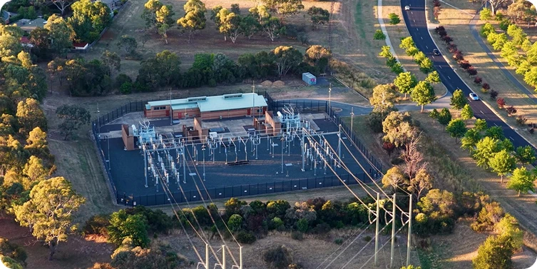
Smart Power Distribution System Solution
As an integrated primary & secondary power distribution solution, it features advanced technology, flexible configuration, high efficiency and intelligence. It fully meets the requirements of intelligent power distribution from 0.4kV to 40.5kV, supporting smart and eco-friendly urban development and providing reliable support for smart grid construction.
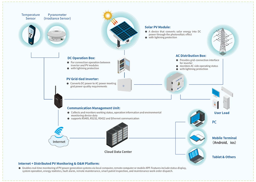
PV-Storage-Charging Smart Microgrid Solution
Drawing on nearly two decades of expertise in power system technology, we integrate PV inverter, power protection, communication and internet technologies to deliver full-lifecycle integrated solutions for distributed PV power stations, including utility-scale and energy storage PV power stations.
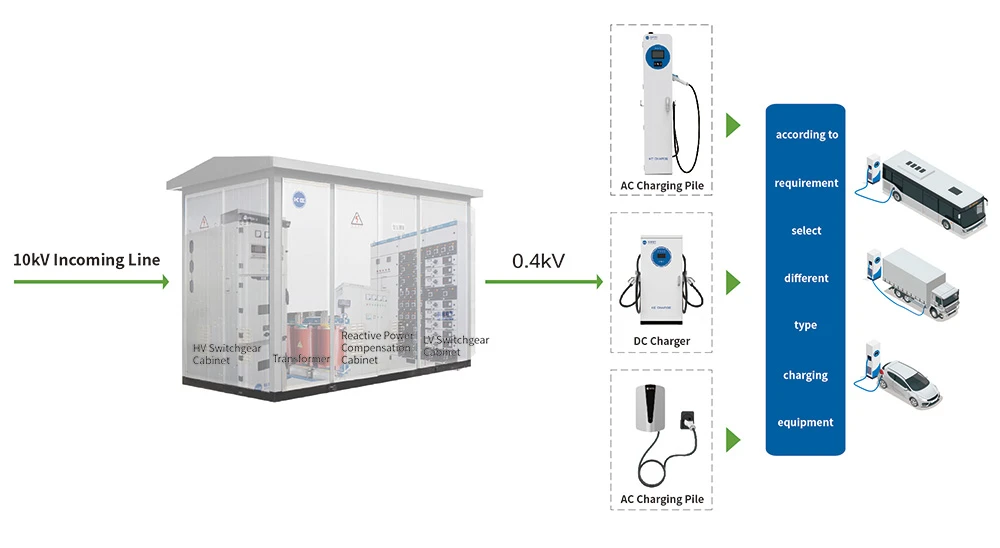
A complete EV charging solution comprising smart charging equipment, cloud platform and mini-program, covering AC and DC chargers, operation platform and customized mini-program development.
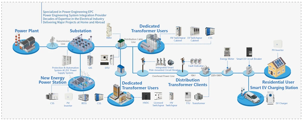
Power Engineering System Integration Solution (EPC)
Kelin Power Engineering EPC leverages the brand, technology, capital and market advantages of Kelin Electric. Focused on power engineering construction, we have established a full lifecycle service model of "Design + Procurement + Construction", striving to deliver premium projects in the power industry.
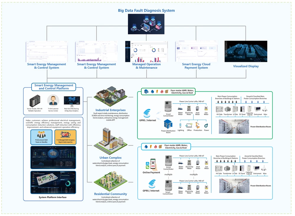
Smart Energy Management & Control Platform
Focused on integrated energy management, and drawing on extensive power system experience combined with the company's full product range, we provide premium integrated energy management and control solutions for enterprise parks, residential communities and urban complexes based on Internet thinking.
Product Parameters
Information on components, accessories, packaging, etc.
• Product completeness: The switchgear is accompanied by a packing list, product certificate, product instruction manual and necessary drawings. Supplied accessories include door keys and spare parts as listed in the packing list.
• MCC package includes two sizes of cable-end sleeves and a quantity of copper lugs for secondary circuits. (To suit crimped copper lugs, multi-core flexible wires are recommended for secondary cables.)
Transportation and storage:
• The device must not be tipped over or subjected to severe vibration.
• When hoisting after unpacking, protective lifting angle brackets should be used, and the angle between the two slings must be ≤120°. Do not use a forklift, lever or pry bar directly against the bottom frame of the device.
• When the device is installed and positioned, if it needs to be moved a small distance, it can be pried at the four corners of the bottom frame.
• Do not arbitrarily disassemble electrical products and parts inside the device.
• Prevent rain and moisture. The ambient temperature should comply with the relevant provisions of this sample.
Ordering instructions:
The user should provide the following information:
• Main circuit scheme number and system diagram;
• Schematic diagram or schematic wiring diagram;
• Detailed specifications and quantity of electrical equipment installed in each cabinet, and fill in the ordering specification sheet;
• Arrangement and combination diagram and floor plan of switchgear.
Find Solutions, Not Just Suppliers
If you are interested in any of our products or would like to make your customized order, please feel free to contact us. We are looking forward to establish successful business relations with you.
Discover More